The report from prop 1/ 2021 translated into English.
Der Bericht aus dem prop 1/ 2021 in Englisch übersetzt.
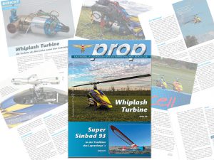
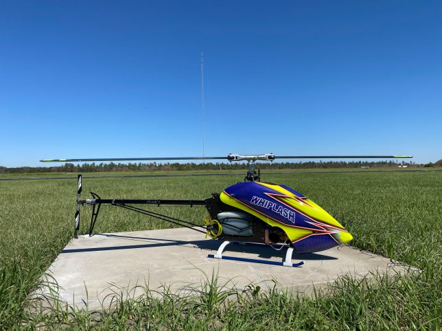
Whiplash Turbine – The Mercedes among the 700 class helicopters
(translation from my prop report)
For many RC pilots, a turbine is the Mercedes of engines, whether in an aircraft, jet, glider or, as in my case, in an RC helicopter.
This wish was reinforced in 2019 when I was in Germany with one of my buddies to check out the Whiplash 730E, which we both fly since 2020. At the airfield where we met with Judith and Josef, the faces behind Miniature Aircraft, the prototype of the WHIPLASH-T II was also on display. At that time, it was still a prototype and powered by the WREN 44i. This is where I caught attention for this type and was immediately fascinated by the idea to power a 3D helicopter with a turbine. With the Whiplash family, Miniature Aircraft is the only manufacturer to offer all types of drives for RC helicopters in one series: Electric, nitro, petrol and turbine. These are not „conversions“, but each model has been specially designed and tested for the respective type of engine.
Due to the COVID-19 situation in Europe, my order was understandably delayed by a few months. However, a lot has happened since then and TURBINE SOLUTIONS had launched a new edition especially designed for the Whiplash-T II.
I ordered my kit and the turbine at the end of 2020 as my “winter project” but unfortunately due to the COVID-19 situation in Europe the order was delayed by a few weeks.
Lets take a look at the model step-by-step now.
Brief insight into the mechanics:
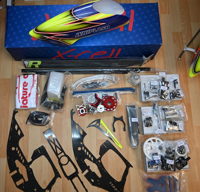
Packing
After opening the packaging, the large and extremely high-quality-looking carbon-fibre side panels are immediately an eyecatcher. Other components, with the exception of the tail tube and the associated rigid drive, as well as the landing skids and the tank, are sorted and packed in individual labelled cardboard boxes depending on the assembly step.
First impression
A close inspection reveals that the plastic parts have been reduced to a minimum and almost all parts are made of high-quality full carbon (without glass fibre or G10 parts, as is quite common with many other manufacturers) and high-quality aluminium. There are only a few parts, such as the ball head cups and the drive pinions, which are made of plastic, but still very high-quality plastic. The CNC-milled gear wheels make an extremely stable and solid impression. The completely painted canopy also leaves nothing to be desired.
Assembly:
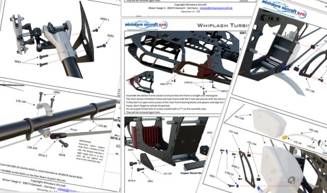
The assembly was divided into several sections. As expected, the easy-to-understand assembly instructions are clearly laid out and are no problem for the ambitious model builder. The complete assembly instructions are available for download.
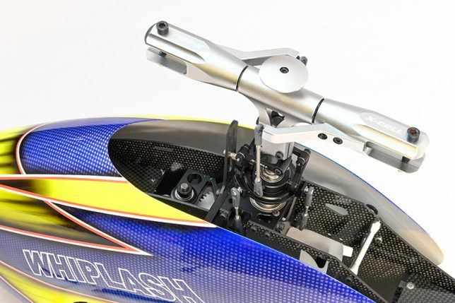
The rotorhead:
With the pre-assembled swashplate, only the steel balls need to be mounted. The thrust bearings of the blade holders are already correctly pre-assembled and greased, so only the linkage arms need to be mounted. After assembling the blade holders and the central piece over the 9mm thick blade bearing shaft, the high fitting accuracy of the individual components is already noticeable for the first time. The black anodised swashplate forms a pleasant contrast to the sandblasted blade holders as well as to the central piece and is therefore also an eye-catcher.
The tail:
As with the main rotor head, these parts are sandblasted and make an extremely solid impression. The tail section impresses with a gear wheel milled from aluminium on the tail rotor shaft, which is driven by a pinion made of polyoxymethylene (POM) on the star drive shaft. The special hard Teflon coating of the aluminium gear wheel in combination with the POM gear wheel results in a maintenance-free tail gear.
In order to achieve the smoothest possible running, the guidance of the rigid drive in the rear tube is also extremely well thought out and implemented with several O-rings per bearing unit. After the final assembly of the rear unit, the completely backlash-free smoothness of the entire rear linkage is immediately noticeable.
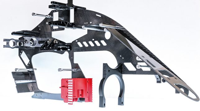
The chassis
In the first step, all the intermediate plates for the components, the black anodised bearing blocks milled from aluminium, the beautiful red turbinemount and the servo mounts are mounted and then screwed onto the first side plate of the chassis together with the necessary braces. Now the chassis is closed with the second chassis plate.
After that, the base assembly is mounted for the first time without fixing it with screw lock, as our turbine still has to be mounted into the mechanics from below. By „pre-mounting“ the base plate, the chassis can be checked for straightness and squareness before installing the turbine. Finally, the unit consisting of the helical main gear, ring gear and freewheel is assembled and also mounted in the chassis. Finally, the clutch unit is assembled with the drive pinion.
Installation of the turbine:
Now the chassis-floor assembly is removed again. After mounting and calibrating the fan wheel with the clutch rotor on the turbineshaft, the complete turbine unit is pushed into the mechanics from below and mounted. The front part of the turbine (also called gas generator), in which the combustion chamber is located, is additionally supported with 4 separate rubber-damped retaining elements.
For the additional components of the turbine, such as the electronics, valves and fuel pump, there are fixed fastening points in the mechanics. For example, there are fixed holes for the valves, where they can be easily fastened with the included screws. Then the floor assembly and the landing skids are mounted.
Final assembly:
After the completion of the chassis with the turbine, the tailsection with the tail struts and the main rotor head are installed as usual. As expected, the entire mechanics make an extremely stable and torsionally stiff impression. I also like the fact that all the gearboxes run quietly and smoothly and that the milled main gear wheel runs perfectly on its track.
The tank is completely mounted on rubber buffers and is only fixed in the intended position at the end. The header tank (also called hopper tank) is included in the delivery. This tank ensures a „bubble-free“ fuel supply to the fuel pump.
Many necessary small parts such as tank pendulums, fuel hoses, connectors, Y-connectors, Velcro straps etc. are also included.
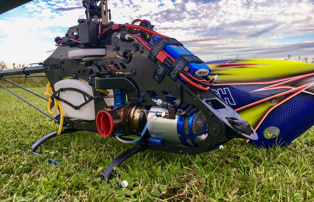
Electronics
The installation of the electronics as well as the routing of all cables and fuel hoses goes smoothly by hand and, in my opinion, needs no further detailed explanation.
My turbinehelicopter uses Futaba servos and the Futaba flybarless CGY 760R. I also need 2 Lipo batteries. One for the power supply of the servos and the FBL, and one for the turbine.
Turbine Solutions
Many turbine pilots, or those who want to become one, know the name WREN Turbines for reliability and good service.
At the beginning of 2019, WREN Turbines was acquired by TURBINE SOLUTIONS, owned by Paul Hardman. The story: Long before Paul acquired WREN Turbines, he worked for the company himself. As his expertise grew, he one day set up his own business and founded TURBINE SOLUTIONS. In 2019, the opportunity arose for Paul to acquire WREN Turbines. TURBINE SOLUTIONS develop and manufactures RC jet and helicopter turbines and offers services for all aspects of RC turbines.
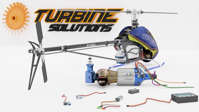
The TS 45i Heli Turbine
In mid-December 2019, the news came that there would be an optimised turbine for the Whiplash from Turbine Solutions, called the „Whiplash Special Edition TS 45i Heli Turbine“. The TS 45i Heli is a further development of the well-known WREN 44i. The TS 45i Heli convinces with a short response time and a high dynamic power development. This is very beneficial for today’s flying styles. The max. power at the output shaft is 7HP / 5.2Kw @ 190,000 rpm and the turbine is „full throttle resistant“. Of course, this turbine is delivered with a paraffin starting system.
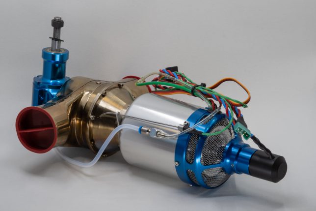
All parts required to operate the turbine are included in the scope of delivery. This also includes the electronic control system (called FADEC or ECU). This regulates or checks all parameters and components of the turbine (e.g. fuel pump, valves, speed, temperature…) necessary for start-up, operation and the cooling process. Data from the control system can be read out via a data terminal or telemetry (using an optionally available telemetry module).
The TS 45i Heli Turbine is a twin-shaft turbine and is therefore based on the same principle as the turbines in manned helicopters.
A two-shaft turbine consists of two stages. The first stage, the so-called gas generator, is similar to a jet turbine and contains the first shaft. In this stage, the paraffin is burned and the entire power is available in the exhaust jet. This exhaust jet now „blows“ onto the second stage of the turbine engine and thus drives a second shaft via a turbine wheel. Hence the term two-shaft turbine. These two shafts are not mechanically connected to each other. The second shaft thus receives the mechanical drive power from the exhaust jet of the first stage. The second shaft turns much slower than the first shaft. The mechanical transmission coupled to the second shaft thus operates at lower speeds than if the mechanical power were taken from the first, high-revving shaft. This has a positive effect on the efficiency of the turbine engine.
An important point is safety when operating model turbines. The exhaust at the turbine outlet reaches temperatures of over 700°C during operation. It is therefore important to ensure that there is nothing flammable in the exhaustarea, e.g. dry grass or similar, and that a CO² fire extinguisher is always to hand when operating a turbine. Basically, it is important to ensure that the exhaust gases from the turbine are led directly into the open air without „touching“ other parts of the helicopter. This is well realised in our trainer model.
Furthermore, a failsafe must be programmed for turbine models, because in the event of a loss of signal, the electronic control system must switch the turbine to idle. After a further 1.5 seconds, the turbine is switched off.
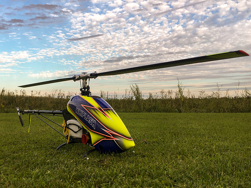
First flight
A turbine is actually easier to start up than a nitro or petrol engine. Just flip the switch and the turbine starts automatically thanks to the paraffin start system.
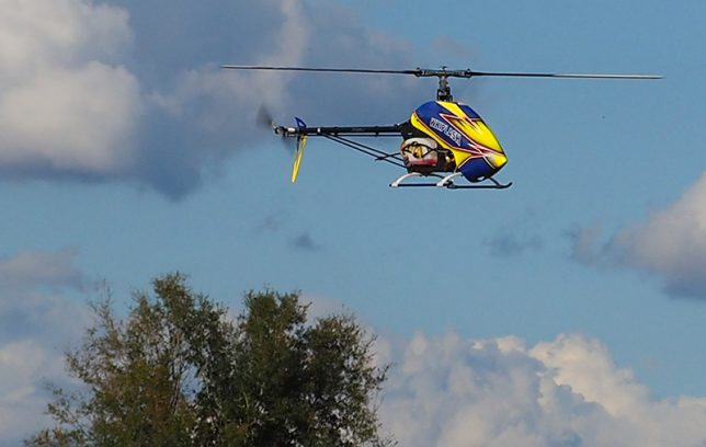
Although I have flown a Whiplash turbine from time to time, it is still something different when it comes fresh from the workbench, so to speak. I felt like I did during my first steps: all the FBL parameters go through your head again and you stand behind the model excited.
Then, after the 1st speed is reached, you give a slight pitch and with every millimetre you get a bigger grin on your face (can also be due to the smell of kerosene). The helicopter floats gracefully and hissing in front of you, the first control commands follow to switch to the sightseeing flight. It’s really something special.
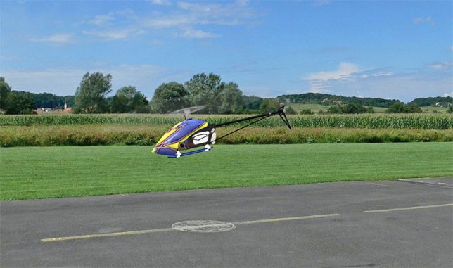
Conclusion
As already mentioned, the Whiplash-T II was specially designed to be powered by a turbine engine. Whether used as a trainer, for more common flights or as a pure 3D machine, the Whiplash-T II and the TS 45i meet all expectations. Not least because of this, Miniature Aircraft once again made history: Mitch Marozas (Team Miniature Aircraft) was the first pilot ever to take part in the legendary 3D freestyle competition „Battle of the brands“ at the IRCHA event in the USA with a turbine-powered helicopter, the Whiplash-T II. His flight thrilled the spectators and proved the performance of the helicopter and the turbine. After all, Mitch took the third place with his turbine powered Whiplash.
Author Michael Peer
Battle of the brands (video)